Get ready, this one is exciting, and long. Sorry RSS readers, this also uses animations.
Translation Lookaside Buffer (TLB)
There are two types of addresses on the PlayStation 2 and modern computers. Virtual and Physical.
Virtual addresses are most important to developers because there is no way to directly access
physical locations without first going through virtual addressing.
Physical addresses are only important if you want to change how virtual addresses are mapped.
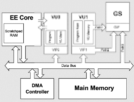
Here is a totally accurate represenation of what it may look like inside of the EE while the EE is accessing memory.
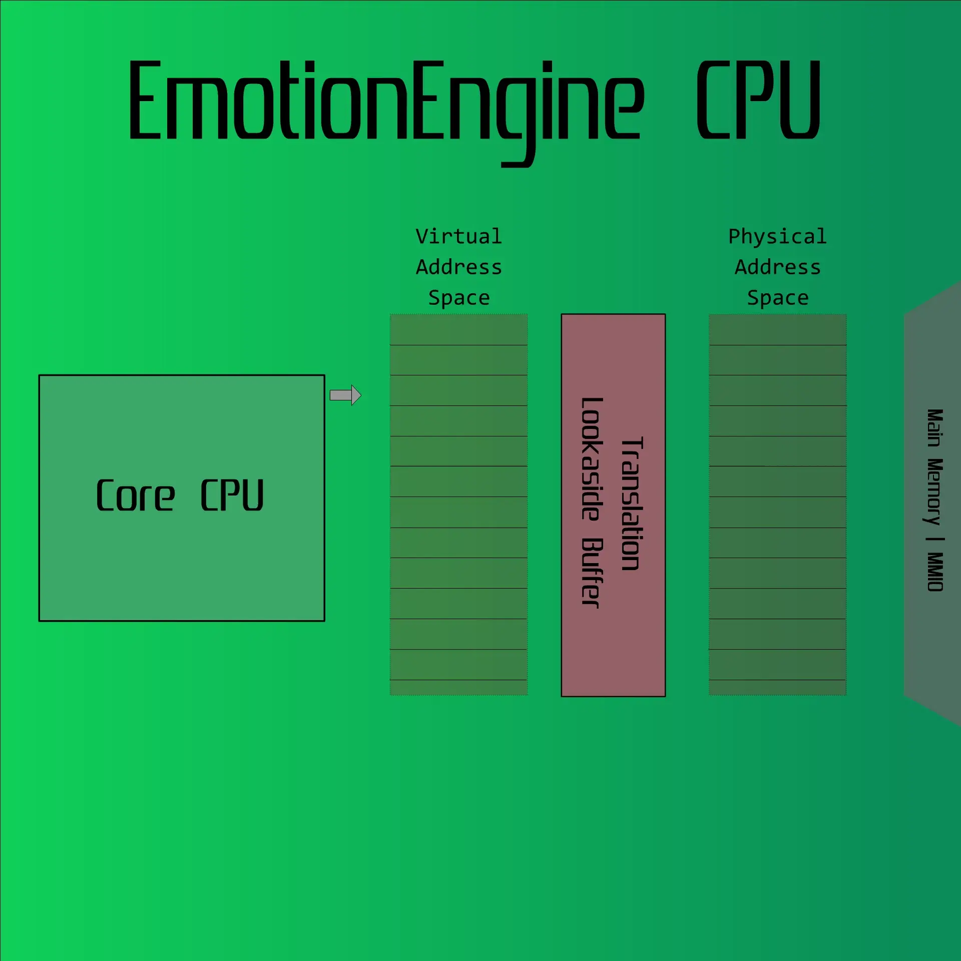
There are multiple “entries” in the Translation Lookaside Buffer which can be modified. These entries map a Virtual Address “page” (illustrated as rectangles in the address spaces) to a Physical Address “page”.
These entries will be referred to as their proper name, “TLB Entries”, from now on.
TLB Entries are very complex when you include odd/even pages and caching options so thankfully Sony provides a default memory mapping for us. The great majority of games do not, and never need to adjust this mapping.
The default mapping can be found on ps2tek.
Scratchpad Ram (SPR)
I’ve used SPR in my post ‘PS2 DMAC Basics’
Essentially, SPR is memory directly located on the EE. This has the benefit of not having to use the main bus to access it. Because you don’t have to use the main bus, it can be much faster to use this memory.
SPR can be used directory through its own virtual address via its TLB entry1, or through the DMAC.
Backtracking a little bit, part of configuring a TLB entry includes the ‘S’ bit. The ‘S’ bit is checked at the second last stage of the TLB mapping process and it simply determines if the virtual address is accessing SPR or not.
Interfacing With the TLB
The EE provides special coprocessor-0 (COP0) instructions and registers to manipulate the TLB.
Instructions
- TLBR - TLB Read
- TLBWI - TLB Write
- TLBWR - TLB Write Random
Registers
- PageMask
- EntryHi
- EntryLo0
- EntryLo1
- Index
- Random
- Wired
- Context
- BadVAddr
I wont bore you with the details of it all2, but firstly you set Index to the index of the TLB entry you want to read/write. Then you can use TLBR or TLBWI to read/write to that entry using the values in the registers listed above.
The most important registers for SPR mapping are EntryHi, which determines what virtual address the entry is for and EntryLo0 which contains the SPR flag.
I wrote some code that iterates through all of the TLB entries until it finds the entry for SPR. Here is the dirty work involved when reading the entries.
tlb_entry_t read_entry(int index)
{
	tlb_entry_t entry;
	// Set Index and Read the Entry
	asm volatile("mtc0 %0, $0\n"
				"sync.p"
				"tlbr\n"
				"sync.p\n"::"r"(index));

	asm volatile("mfc0 %0, $2\n"
				 "mfc0 %1, $3\n"
				 "mfc0 %2, $5\n"
				 "mfc0 %3, $10\n"
				 "sync.p\n":
				 "=r"(entry.EntryLo0),
				 "=r"(entry.EntryLo1),
				 "=r"(entry.PageMask),
				 "=r"(entry.EntryHi));
	entry.Index = index;

	return entry;
}
When used it resulted in this
Index: 0
EntryLo0: 0x80000006
EntryLo1: 0x00000006
PageMask: 0x00000000
EntryHi: 0x70000000

SPR (bit 31 of EntryLo0) is set!
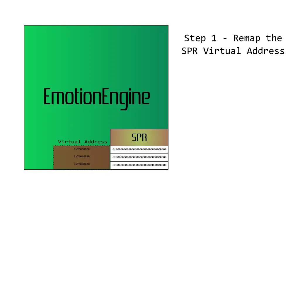
Okay, so the first default entry is for SPR, easy enough. We can verify this is correct because SPR is known to be mapped at virtual address 0x70000000 and this entries EntryHi register value matches that.
Remapping an Entry
Part of the test is moving the virtual address of SPR to a different location, to remap the existing SPR TLB entry, we simply have to change EntryHi and do a tlbwi to commit this new value into the TLB.
	u32 newEntryHi = 0x80000000;
	asm volatile(
		"mtc0 %0, $10\n"
		"sync.p\n"
		"tlbwi\n"
		"sync.p\n"::"r"(newEntryHi));
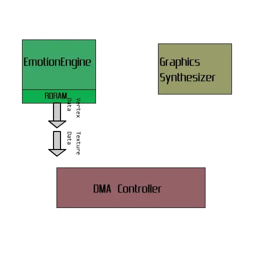
Doing the Test
We know that SPR can be accessed from the DMAC. On real hardware, this completely avoids the TLB. We can consider what we read from the DMAC to be the truth of what is in SPR.
The idea is to
- Remap SPR to 0x75000000 (from 0x70000000)
- Write to 0x75000000
- DMA transfer data back from SPR
- See if what we wrote to 0x75000000 is also what the DMA transfer read
Here is a visualization:
And here is the code:
int test_spr_remap_works()
{
	// Clear SPR data
	u128* spr = (u128*)0x70000000;
	spr[0] = 0x0;
	spr[1] = 0x0;
	spr[2] = 0x0;

	remap_spr(0x75000000);

	// Write data to the newly mapped address
	qword_t* spr_address = (qword_t*)0x75000000;
	spr_address[0].dw[0] = 0x1111111111111111;
	spr_address[0].dw[1] = 0x1111111111111111;
	spr_address[1].dw[0] = 0x2222222222222222;
	spr_address[1].dw[1] = 0x2222222222222222;
	spr_address[2].dw[0] = 0xFFFFFFFFFFFFFFFF;
	spr_address[2].dw[1] = 0xFFFFFFFFFFFFFFFF;

	FlushCache(0);

	// Read data from the SPR using the DMAC
	qword_t spr_dma[3] __attribute__((aligned(16)));

	*R_EE_D8_MADR = (uiptr)spr_dma;
	*R_EE_D8_SADR = 0x0; // Relative to the start of SPR
	*R_EE_D8_QWC = sizeof(spr_dma) / sizeof(u128);
	*R_EE_D8_CHCR = 0x100;

	while(*R_EE_D8_CHCR & 0x100);

	FlushCache(0);

	int is_same = !memcmp(spr_dma, spr_address, sizeof(spr_dma));

	// Restore the original SPR address
	remap_spr(0x70000000);

	return is_same;
}
And that’s about it. On DobieStation and Play!, it does not work and hangs the ELF.
I am unable to test hps2x64.
As for PCSX2, originally it did not work. However, after some investigation, the
systems were already in place to properly support remapping SPR. It was for some
reason gated behind a hard-coded check for the original 0x70000000 address.
Once my PR to PCSX2 is merged, this method will not
work on PCSX2.
This led me down a rabbit hole and to probably one of my favourite discoveries I’ve made regarding weird PlayStation 2 optimizations. More on that in my next article :^).
I give this method a 5/5 in difficulty. It is quite complex in my opinion and if you’re not careful, you can easily deadlock the system.
]]>
Changing it up from our past methods, we will be using the GS (Graphics Synthesizer) to detect if we are running under an emulator.
It’s really difficult to call the GS a GPU, it’s a lot more simple than what most would consider a GPU. The GS is just a rasteriser, the heavy lifting is written by the developer on VU1. If you’d like more information I recommend checking out this writeup of the PS2 hardware to see everything the GS can do.
Because the GS is simple it’s also quite fast. If you’re interested, I have a previous post benchmarking different methods of clearing a framebuffer on the GS linked here. Despite being fast, the GS isn’t instant. In this context, concept of the GS being busy drawing is called “backpressure”. Sony implemented some ways to properly synchronize the GS with the EE (main CPU). One of these methods is how we will calculate the GS processing time.
GS Signals
There are three types of GS Signals. You trigger these by writing to their respective register (showcased in the implementation).
- SIGNAL
- LABEL
- FINISH
SIGNAL sets a bit in the GS status register and optionally generates an interrupt without waiting for the GS to finish the current drawing process. If SIGNAL is written to while a previous SIGNAL interrupt state hasn’t been cleared, the GS will halt until this interrupt status has been cleared.
LABEL writes to a special field in the SIGLBLID register. There is no interrupt for this signal.
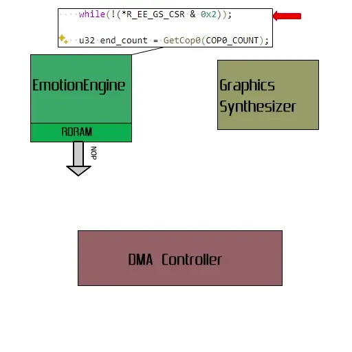
FINISH is much like SIGNAL, where it sets a status bit and optionally an interrupt, but successive writes to FINISH do not halt the GS. Adding a write to the FINISH register at the end of your drawing packet allows the EE to know when the GS has finished your drawing process. This is going to be the signal we use to time the GS.
Here is an example of how using FINISH can syncronise the GS and the EE
Note that this animation is assuming that there is no GS backpressure, the transferred data is immediately consumed by the GS. Another note, the time it takes the data (arrows) to go from EE RAM to the GS is the DMA transfer time. DMA transfer time is required for emulating the majority of games, but is not important for us now.
The Implementation
The PS2 has a few ways to time things, the easiest is using COP0 register called Count. Count is a 32 bit counter that increments every clock cycle. If we get the count before we start our EE->GS DMA transfer, then the count after the GS has finished, we can see how many cycles the drawing process took.
Ideally we would be drawing large sprites with texture mapping, alpha blending, fogging, etc to really make the slowest possible drawing packet. To do this would require a bunch of boilerplate drawing environment setup. So for this example, we will avoid that and write to NOP the maximum amount of NLOOP times. The exact details are irrelevant, we are writing to NOP a lot.
Instead of breaking everything down, I opted to instead show you a heavily commented example of the implementation.
int isGSBackpressurePresent()
{
    // Allocate some memory on the heap for our GS packet
    qword_t* gs_packet = aligned_alloc(16, sizeof(qword_t) * (0x7FFF + 1));
    qword_t* q = gs_packet;

    // Set our TAG (header), inform the GS that we will send 0x7FFF qwords of
    // register writes
    PACK_GIFTAG(q, GIF_SET_TAG(0x7FFF, 1, 0, 0, 0, 1), GIF_REG_AD);
    q++;
    // Write 0x7FFE NOPS
    for(int i = 0; i < 0x7FFE; i++)
    {
        PACK_GIFTAG(q, 0, GS_REG_NOP);
        q++;
    }
    // Finish off the packet with a write to FINISH
    // Once the GS is done processing the above NOPs, it will process this
    // and set the FINISH status bit
    PACK_GIFTAG(q, 1, GS_REG_FINISH);
    q++;

    FlushCache(0);

    // Enable FINISH event / clear any past events
    *R_EE_GS_CSR = 0x2;

    // Send the packet via the DMAC
    *R_EE_D2_MADR = (u32)gs_packet;
    *R_EE_D2_QWC = (q - gs_packet);

    // Get our cycle count before we send the packet
    u32 start_count = GetCop0(COP0_COUNT);

    // Start the DMAC transfer
    *R_EE_D2_CHCR = 0x101;

    // PCSX2 emulates DMAC transfer time (unless instant DMA is enabled).
    // We don't care about that so we don't wait for the transfer to finish
    // while(!(*R_EE_D2_CHCR & 0x100));

    // Wait for the GS to process the final FINISH write by spinning
    // on the FINISH status bit
    while(!(*R_EE_GS_CSR & 0x2));

    u32 end_count = GetCop0(COP0_COUNT);

    free(gs_packet);

    // Takes around 400_000 to 427_000 cycles on a real PS2
    // Assume that any less than 300_000 cycles is due to lack of backpressure
    // emulation
    return (end_count - start_count) > 300000;
}
To extend our previous animation, this is what the above implementation does.
Currently no emulators (PCSX2, Play!, DobieStation, hps2x64*) emulate this behaviour1.
I rate this one a 2.5/5 in difficulty. You have to build a giant packet, clog up the GS for a little bit, and spin the EE for a bunch of cycles. It’s not necessarily slow or very complex, but there are surely better alternatives.
Why Is This Not Emulated?
Emulating this perfectly would be quite laborious. As I said previously, an ideal test would push the GS to its limits by using all of the GS features. Fully emulating backpressure would require emulating DRAM latency and the delay imposed by page breaks, texture cache misses and penalties from using alpha blending, fogging, gouraud shading, and more. The effort to properly hardware test all of this and implement it would be effectively pointless. Very few games suffer from missing backpressure2. Not only that, the performance gained by not emulating backpressure is definitely worth it being missing.
-
I can’t actually test hps2x64, but by my analysis of the code, I do not immediate see any GS cycle counting system. ↩
-
I was informed of an experimental PCSX2 that estimates backpressure based on the size of a DMA packet. However, I’m not entirely sure if that fixes the games affected by the lack of backpressure emulation, nor have I had the chance to play around with it as of now. ↩
This is a pretty straightforward method. This one can be done on VU1, VU0 micro mode or VU0 macro mode. For simplicity, I will do it with VU0 macro mode, where VU0 is used as a coprocessor. That way it can be done directly on the EE CPU without dealing with VU programs.
Welcome to hell PS2 Floating Point
If you look at any multiplication instruction (MUL,MULi, etc) in the VU developer manuals, you will see this remark:
There is an operation error of 1 bit in multiplication, so the value multiplied by 1 may not be the same as the original value. By using VF[fs] as a multiplicand, the results of multiplication with 1 are guaranteed to be accurate.
It’s a little bit loaded but the gist of it is, with multiplication operations 1 * X is not guaranteed to result in X, unlike X * 1 which is.
The exact reason why a bit is lost is not known to me, whoever decides to implement software floating point for the PS2 will have to figure that out and report back :^)
Abusing it
First things first, we need to figure out a number that triggers this issue. The easiest way to do that is to brute force it. Thankfully I’ve already done that in the past. The list of the first 250 numbers (with 0.5 increments) that have the issue can be found in a gist here.
129.5 will be our target number for this detection.
int isVUMulErrorPresent()
{
    float in[4] __aligned(16) = {129.5f,0.0f,0.0f,0.0f};
    float out[4] __aligned(16) = {0.0f,0.0f,0.0f,0.0f};
    asm __volatile__(
        "QMTC2 %1, $vf1\n"          // Set VF1 to 129.5f
        "VADDw $vf2, $vf0, $vf0w\n" // VF2 = vf0[w] = 1
        "VMUL $vf1, $vf2, $vf1\n"   // VF1 = 1 * 129.5f
        "QMFC2 %0, $vf1\n"          // Load the number back to the EE
        : "=r"(out[0])
        : "r"(in[0]));
    return in[0] != out[0];
}
Like I said, it’s pretty straightforward. Load 1 and a special number into a register, multiply them, check the result.
Currently no emulators (PCSX2, Play!, DobieStation, hps2x64) emulate this behaviour.
The difficulty of this one is definitely a 1/5.
I’ll choose a difficult one next time.
I’m intending on making this a little series. For each method I’ll rate the difficulty, provide an explanation, and provide some code.
The VU0 Macro Mode (COP2) Pipeline
Like any other processor, VU0 instructions take time. This unit of time is usually in cycles. Instead of instructions being “blocking”, where, as soon as they are executed the next instruction always waits for the previous to continue, you asynchronously execute them in what’s known as pipelines.
Processor development is out of scope for this post so I wont get into the theory of pipelines. I will however, list the pipelines available for VU0 Macro mode.
- General Instructions
- VDIV/VSQRT
- VRSQRT
- VCALLMS/VCALLMSR
VCALLMS/VCALLMSR and VRSQRT are not going to be used here and can be ignored. The important part is how the ‘General Instructions’ and ‘VDIV/VSQRT’ are used. ‘General Instructions’ mostly read and write to and from the VF00 to VF31 registers.
VADD VF03, VF01, VF02 ; VF03 = VF01 + VF02
VMUL VF05, VF03, VF04 ; VF05 = VF03 * VF04
The VDIV and VSQRT instructions write to a special register called Q.
VDIV Q, VF01, VF02 ; Q = VF01 / VF02
Pipeline Stalls
Let’s investigate the example above. VADD has a Throughput/Latency of 1/4, this means after 4 cycles the destination register will contain the result.
The follow code however, still works as expected.
VADD VF03, VF01, VF02 ; VF03 = VF01 + VF02
VMUL VF05, VF03, VF04 ; VF05 = VF03 * VF04
This is because, the pipeline stalls until VF03 is ready (once VADD finishes). Although it looks like there is a 1 cycle difference in the assembly, once we account for the pipeline stall (due to register dependency), VMUL can’t fully execute until the 5th cycle. This is a property of the ‘General Instruction’ pipeline.
The VDIV / VSQRT pipeline is a little different however.
VDIV has a Throughput/Latency of 7/7, this means after 7 cycles the destination register (Q) will contain the result of the division.
VDIV Q, VF01, VF02  ; Q = VF01 / VF02
VADDq VF03, VF00, Q ; VF03 = Q
What’s different is that there is no pipeline stall for Q here, VADDq will immediately execute, disregarding
the fact that VDIV is still executing. The result of VADDq is undefined in our example.
This isn’t a strange quirk or footgun, there are uses for this, but that is off topic now.
If you need to get the VDIV result immediately, there is a handy instruction available. This code is perfectly valid.
VDIV Q, VF01, VF02  ; Q = VF01 / VF02
VWAITQ
VADDq VF03, VF00, Q ; VF03 = Q
What’s not emulated
The following information is correct as of the current PCSX2 version 1.7.5865.
So I hear you’re asking, what’s the issue? The issue is that PCSX2 ignores the VDIV/VSQRT pipeline. VDIV/VSQRT writes the result immediately. At this point in time, it’d be somewhat detrimental to performance to track the pipeline. For the games that do use this pipeline in arguably mean ways, it’s easily remedied by what we call a ‘COP2’ patch. In the easiest case, you swap the VDIV and whatever uses Q and it works out fine. Because it’s such an easy fix, no one has opted to implement this pipeline, and you can argue that it works out to be a net positive.
Remember our undefined, bad example using VDIV? This works perfectly fine in PCSX2.
VDIV Q, VF01, VF02  ; Q = VF01 / VF02
VADDq VF03, VF00, Q ; VF03 = Q
And if you’re wondering, VWAITQ doesn’t do anything in PCSX2, it’s just a VNOP.
Finally, detecting the lack of VDIV pipeline
I think I have you primed for this now. The solution is incredibly simple despite its complex explanation. There are ways you can shave off one or two instructions. I’ll leave that as an exercise to the reader.
    ; Let the VF1x register hold 2.0f
    ; VF0x is always 0.0f

    ; Initialize the Q register to 1.0f
    VDIV Q, VF1x, VF1x ; Q = 2.0f / 2.0f = 1
    VWAITQ             ; Wait for VDIV to finish

    VDIV Q, VF0x, VF1x ; Q = 0.0f / 1.0f = 0
    ; Immediately use Q. If the pipeline is not emulated Q is 0
    ; If the pipeline is emulated, VDIV is still executing and Q = 1
    ADDq, VF1, VF0, Q  ; VF1 = 0 + Q

   ; If VF1 is 0, the pipeline is not emulated
   ; If VF1 is 1, the pipeline is emulated
And in C
int isVDIVPipelined()
{
    float num __aligned(16) = 2.0f;
    asm __volatile__(
        "QMTC2 %1, $vf1\n"        // Set VF1 to 2.0f
        // Initialize the Q register to 1.0f
        "VDIV $Q, $vf1x, $vf1x\n" // Q = 2.0f / 2.0f = 1
        "VWAITQ\n"                // Wait for VDIV to finish
        "VDIV $Q, $vf0x, $vf1x\n" // Q = 2.0f / 2.0f = 1
        // Immediately use Q. If the pipeline is not emulated Q is 0
        // If the pipeline is emulated, VDIV is still executing and Q = 1
        "VADDQ $vf1, $vf0, $Q\n"  // VF1 = 0 + Q
        "SQC2 $vf1, %0\n"         // Load back the number to the EE
        : "=m"(num)
        : "r"(num));
    return num == 1.0f;
}
Currently the only emulator with VDIV pipeline support was DobieStation out of PCSX2, Play!, and hpsx64.
I rate the difficulty of this one a 2/5.
]]>If you need a quick refresher, here is a TLDR:
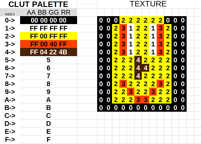
When using indexed texture formats, you upload both a look up table (CLUT) and your indexes. Instead of each texel being 32/24/16 bits of colour, it can instead be an index number into this CLUT (only 8 or 4 bits per texel). This in turn saves massive amounts of memory.
GS Texel Storage Formats
Let’s take a look at the ways the GS can store and load texels.
’#’ Denotes unused bits
PSMCT32
31                               0
├─────────────────────────────────┤
│             RGBA32              │
└─────────────────────────────────┘

PSMCT24
31     24                        0
├───────┼─────────────────────────┤
│ ##### │         RGB24           │
└───────┴─────────────────────────┘

PSMCT16
31              16                0
├────────────────┼────────────────┤
│     RGBA16     │     RGBA16     │
└────────────────┴────────────────┘

PSMT8
31      24       16       8       0
├────────┼────────┼───────┼───────┤
│  ITEX8 │  ITEX8 │ ITEX8 │ ITEX8 │
└────────┴────────┴───────┴───────┘

PSMT8H
31     24                         0
├───────┼─────────────────────────┤
│  I8   │ ####################### │
└───────┴─────────────────────────┘

PSMT4
31     24       16      8       0
├───┬───┼───┬───┼───┬───┼───┬───┼
│I4 │I4 │I4 │I4 │I4 │I4 │I4 │I4 │
└───┴───┴───┴───┴───┴───┴───┴───┘

PSMT4HH
31 24                             0
├───┼─────────────────────────────┤
│I4 │ ########################### |
└───┴─────────────────────────────┘

PSMT4HL
31 24   28                        0
├───┼───┼─────────────────────────┤
│###│I4 | ####################### |
└───┴───┴─────────────────────────┘
What’s important to note is the unused bits. The indexed formats PSMT8H and PSMT4H(H/L) completely ignore the bottom 24 bits. And if you’re paying close attention you might have noticed that the PSMCT24 format ignores the top 8 bits.
Combining CT24 and Index High Storage Formats
By utilising the CT24 colour format for frame-buffers and textures, we can store both an RGB24 texture and one 8-bit texture or two 4-bit textures at the same location in memory (by using PSMT4HL and PSMT4HH).
Notice how I said frame-buffers? That’s right, if you don’t require the 8 bits of alpha in CT32, but need a colour depth greater than the CT16 format, you can put your indexed textures in the same memory as your frame-buffer and z-buffer. Just use the CT24 and Z24 formats.
Unfortunately, the graph (the one in the ps2sdk) and gskit vram allocators are basic and do not perform any sort of optimizations like this. If someone wants an intermediate project, a smarter vram allocator for the PS2 could be a project for you.
If you want to see an example of this optimization in action, I have a git repository with some code and a binary.
My font library also enables you to upload the itex data into the framebuffer, although I’d call that library far from user friendly :^)
I’ve recently added an atom feed. If you’d like to track my posts, add it to your Atom/Supported RSS readers. https://fobes.dev/feed.xml
Thanks for reading.
]]>Problem 1
I’ve been having an issue with the PS2 SDK, using my discord messages for reference, I’ve first run into this since the middle of 2023.
It’s pretty simple, load any PS2SDK ELF, soft reset with ps2link, and load the elf again. This will result in a TLB miss (crash). Investigating, I found that the miss originates in libcglue timezone startup code. Because this is weakly linked, providing an empty stub ‘fixes’ the problem.
void _libcglue_timezone_update(){}

int main()
{
    // do your fun PS2 stuff here, just don't use any timezone stuff
}
I didn’t investigate further. I chalked it up maybe something with reentry within newlib, or maybe the function is just broken. I don’t know much about reentry or timezones so I told anyone who ran into this issue to add that stub and to not use timezones.
Problem 2
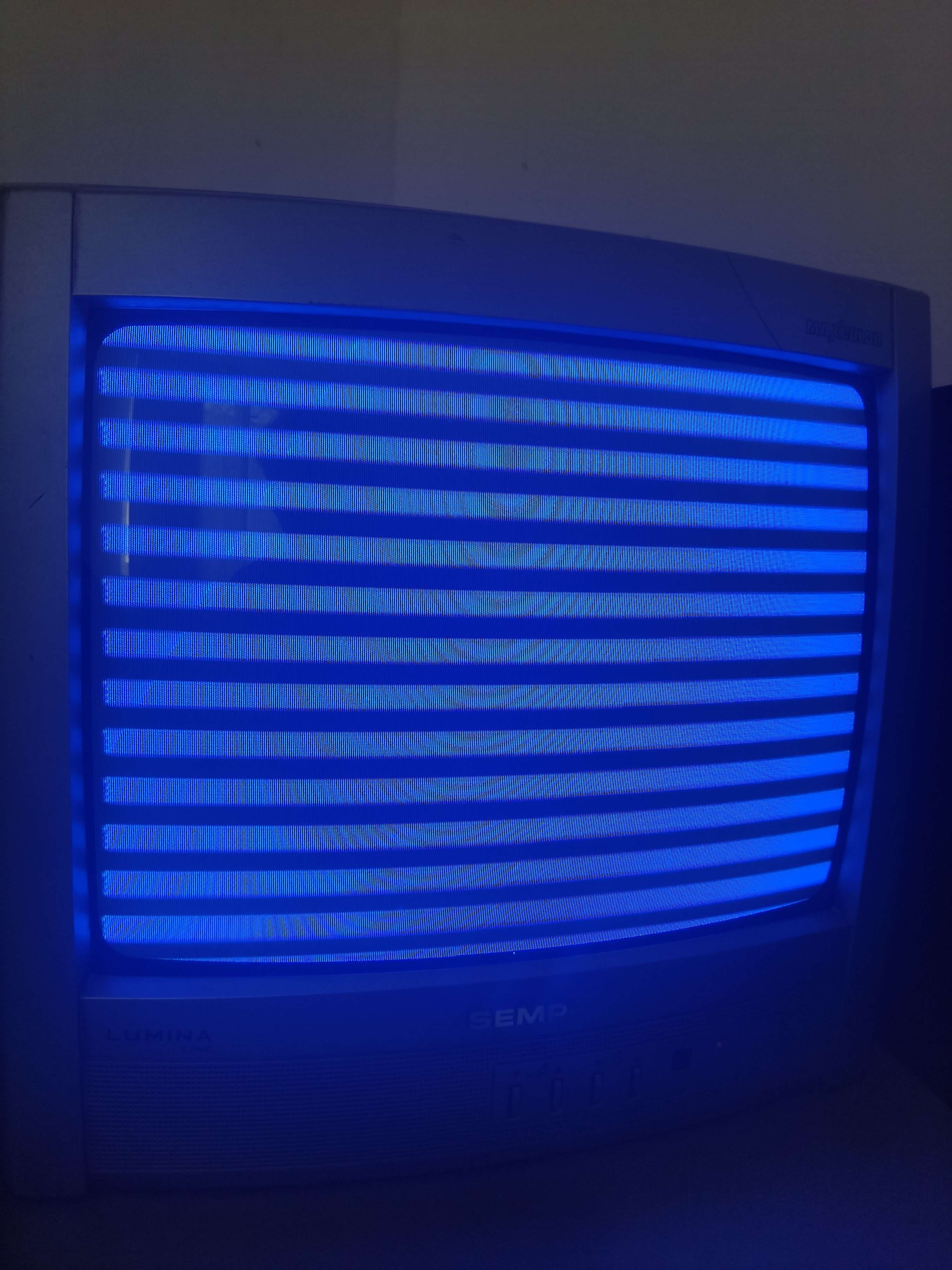
A few months later, someone tells me that after a ps2link reset, their graphics are broken. To be more specific, there are 32 pixel height alternating strips of their clear colour and black. My thought was that the zbuffer is somehow pointing to the framebuffer and that what we are seeing is the zbuffer clearing each bottom half of the page. If you’ve taken a look at my fast clearing post, this will make some sense ;)
After cloning their code and adding some logging, sure enough after a soft reset the framebuffer and zbuffer were pointing to the same page address. 0xFFFFFFFF.
That’s definitely not right.
If you’re curious about how this allocation happens, it’s pretty straightforward, no reason for this to go wrong.
u32 fbp = 0;
u32 zbp = 0;
void alloc_vram()
{
    fbp = graph_vram_allocate(width,height,format,ALIGN_PAGE);
    zbp = graph_vram_allocate(width,height,zformat,ALIGN_PAGE);
}
libgraphs vram allocator is dumb, it’s just linear which is good enough if you’re not tight on vram. Because it’s so simple, I cursed at ps2link for not resetting the vram pointer inside of graph, and recommended calling graph_vram_clear() before starting your first allocation.
At this point, I swore to never use ps2link reset. It just was too unreliable.
Problem Solving
Just a couple days ago I witnessed someone get caught in the timezone issue. I was in a good mood and decided I wanted to figure out what is happening so this footgun doesn’t blow another persons foot off. If I traced the instruction causing the TLB miss I’d end up somewhere in ‘memmove’, with not a good stack frame.
I decided to start from the top instead, starting with _libcglue_timezone_update(). I further narrowed it down to setenv().
setenv() is part of newlib. Digging even deeper into newlib I ended up here.
int
_setenv_r (struct _reent *reent_ptr,
   const char *name,
   const char *value,
   int rewrite)
{
  static int alloced;        /* if allocated space before */
  register char *C;
  int l_value, offset;
  ...
The main thing that caught my eye was that static local, alloced.
Static locals are essentially globals with local scope. If you initialize a static local like so ‘static int alloced = 1’, that local will be initialized only once, even if that line is ‘executed’ multiple times. I don’t like static locals, if you’re not careful you can easily interpret them as being initialized every time a function is called. But that’s not so important here.
I immediately thought back to that vram allocation issue.
Adding logging to newlib was going to be a hassle. Instead, I wrote a test to see if I can reproduce it.
static int global_variable;

int main(void)
{
    printf("!!global_variable = %d\n", global_variable);
    global_variable = 1;

    static int local_variable;

    printf("!!local_variable = %d\n", local_variable);

    local_variable = 1;
    SleepThread();
}
I loaded this up and these are the results:
> ps2client execee host:playground.elf

global_variable = 0
local_variable = 0

> ps2client reset
> ps2client execee host:playground.elf

global_variable = 1
local_variable = 1
That, is, not, good, at, all.
What if it’s just being placed in the wrong section?
> mips64r5900el-ps2-elf-objdump -x playground.elf | grep variable
    0011ff14 l     O .bss 00000004 global_variable
    0011ff10 l     O .bss 00000004 local_variable.0
Nope, the .bss is zero initialized (just like all uninitialized globals). These being here is correct.
What if ps2link is for some reason skipping the __start section?
(This was wasted time as the SCE toolchain compiled homebrew worked fine.)
> mips64r5900el-ps2-elf-objdump -d playground.elf | grep start
    00100b00 <__start>:

> ps2client execee host:playground.elf
Loaded, host:playground.elf
start address 0x100b00
Nope, the start address matches __start.
What if the crt code is wrong?
I decided to try and debug the __start routine that is supposed to clear the .bss section. I wasn’t too convinced that this was the problem. This all made sense when I read it many, many times.
The code in question looked like this.
/*
 * First function to be called by the loader
 * This function sets up the stack and heap.
 * DO NOT USE THE STACK IN THIS FUNCTION!
 */
void __start(struct sargs_start *pargs)
{
    asm volatile(
        "# Clear bss area"
        "la   $2, _fbss"
        "la   $3, _end"
        "1:"
        "sltu   $1, $2, $3"
        "beq   $1, $0, 2f"
        "nop"
        "sq   $0, ($2)"
        "addiu   $2, $2, 16"
        "j   1b"
        "nop"
        "2:"
        "                       \n"
        "# Save first argument  \n"
        "la     $2, %0 \n"
        "sw     $4, ($2)        \n"
        "                       \n"
        "# SetupThread          \n"
        "la     $4, _gp         \n"
        "la     $5, _stack      \n"
        "la     $6, _stack_size \n"
        "la     $7, %1	        \n"
        "la     $8, ExitThread  \n"
        "move   $gp, $4         \n"
        "addiu  $3, $0, 60      \n"
        "syscall                \n"
        "move   $sp, $2         \n"
        "                       \n"
        "# Jump to _main      	\n"
        "j      %2           \n"
        : /* No outputs. */
        : "R"(args_start), "R"(args), "Csy"(_main));
}
I opened it in PCSX2s debugger, but noticed something strange. It was wrong.
> mips64r5900el-ps2-elf-objdump -d playground.elf --disassemble=__start

001017b0 <__start>:
  1017b0:  3c020016  lui    v0,0x16
  1017b4:  3c030016  lui    v1,0x16
  1017b8:  24427acc  addiu  v0,v0,31436
  1017bc:  ac440000  sw     a0,0(v0)
  1017c0:  3c040017  lui    a0,0x17
  1017c4:  2484bf70  addiu  a0,a0,-16528
  1017c8:  3c050000  lui    a1,0x0
  1017cc:  24a5ffff  addiu  a1,a1,-1
  1017d0:  3c060002  lui    a2,0x2
  1017d4:  24c60000  addiu  a2,a2,0
  1017d8:  24677988  addiu  a3,v1,31112
  1017dc:  3c080011  lui    a4,0x11
  1017e0:  25088fe0  addiu  a4,a4,-28704
  1017e4:  0080e025  move   gp,a0
  1017e8:  2403003c  li     v1,60
  1017ec:  0000000c  syscall
  1017f0:  08040018  j      100060 <_main>
  1017f4:  0040e825  move   sp,v0
  1017f8:  03e00008  jr     ra
  1017fc:  00000000  nop
Where is our bss zeroing loop!?
I tried adding nops, I tried changing the inputs and outputs,
messing with volatile qualifiers, disabling optimizations, nothing worked.
Until I realised.
That entire section of assembly is missing newlines.
The first line is a comment.
The entire portion of assembly that handles zeroing our bss section, is a comment.
You see, with inline assembly you need to use newlines (\n) to denote the end of a line. After GCC gave our assembly to the assembler, it looked like this.
# Clear bss areala   $2, _fbssla   $3, _end1:sltu   $1, $2, $3beq   $1, $0, 2fnopsq   $0, ($2)addiu   $2, $2, 16 <the rest of the bss loop>
# Save First argument
la     $2, %0
sw     $4, ($2)
<the rest of the assembly>
Sure enough, adding the newlines (and fixing the formatting) fixed the global variable sample above and the timezone issues. Soft resetting the PS2 is now reliable!
The related pull request can be viewed here.
I think uyjulian summed it up best, “Now that’s a fun issue.”
]]>SIMD essentially allows you to do maths on multiple numbers at a time. This is faster for a few different reasons, one of which being less work for the instruction cache. If you’re curious about the optimizations related to these concepts, check out loop unrolling or vectorization.
Here is an example of two ways to achieve a broadcast multiplication, but one is using SIMD.
* Using GCC 13.2 with flags -O3 and -mno-sse for the unoptimized version.
-
// Multiply the 4 elements in the array by the first element in the array // This is called a broadcast multiply void unoptimized_array_bc_mult(float in[4]) { in[3] *= in[0]; in[2] *= in[0]; in[1] *= in[0]; in[0] *= in[0]; } void optimized_array_bc_mult(float in[4]) { // Load the array into a vector register // arr = {in[0], in[1], in[2], in[3]} __m128 arr = _mm_load_ps(in); // Load the first element into all elements in another register // {in[0], in[0], in[0], in[0]} __m128 multiplier = _mm_load1_ps(in); // Multiply the two vectors // multiplier = {in[0], in[1], in[2], in[3]} // X // {in[0], in[0], in[0], in[0]} arr = _mm_mul_ps(arr, multiplier); // Load it back to the array _mm_store_ps(in, arr); } -
unoptimized_array_bc_mult:
    fld     DWORD PTR [rdi]
    fld     DWORD PTR [rdi+12]
    fmul    st, st(1)
    fstp    DWORD PTR [rdi+12]
    fld     DWORD PTR [rdi+8]
    fmul    st, st(1)
    fstp    DWORD PTR [rdi+8]
    fld     DWORD PTR [rdi+4]
    fmul    st, st(1)
    fstp    DWORD PTR [rdi+4]
    fmul    st, st(0)
    fstp    DWORD PTR [rdi]
    ret

optimized_array_bc_mult:
    movss   xmm0, DWORD PTR [rdi]
    shufps  xmm0, xmm0, 0
    mulps   xmm0, XMMWORD PTR [rdi]
    movaps  XMMWORD PTR [rdi], xmm0
    ret
Anyways, enough of x86, where is the EE mips!
The EE FPU
The PS2’s EE doesn’t directly handle floating point operations, this is handled with the COP1 FPU (Floating Point Unit). When developing however, this is seamlessly handled by the compiler. Unless you’re manually writing assembly, this fact doesn’t matter to you. An easy trick to spot an FPU instruction is to look for a 1 or .s suffix.
-
float cop0_add(float a, float b) { return a + b; } -
00101138 <cop0_add>:
  03e00008        jr      ra
  # add.s is an FPU instruction!
  460d6000        add.s   $f0,$f12,$f13
Sorry, no colour formatting :(
So, if I were to compile the previous unoptimized multiply function for the PS2, it would look like this.
00101138 <unoptimized_array_bc_mult>:
  101138:       c4800000        lwc1    $f0,0(a0)
  10113c:       c483000c        lwc1    $f3,12(a0)
  101140:       c4820008        lwc1    $f2,8(a0)
  101144:       c4810004        lwc1    $f1,4(a0)
  101148:       460018c2        mul.s   $f3,$f3,$f0
  10114c:       46001082        mul.s   $f2,$f2,$f0
  101150:       46000842        mul.s   $f1,$f1,$f0
  101154:       46000002        mul.s   $f0,$f0,$f0
  101158:       e483000c        swc1    $f3,12(a0)
  10115c:       e4820008        swc1    $f2,8(a0)
  101160:       e4810004        swc1    $f1,4(a0)
  101164:       03e00008        jr      ra
  101168:       e4800000        swc1    $f0,0(a0)
  10116c:       00000000        nop
The FPUs Cousin, VU0
The PS2 actually has two more “FPUs”. Vector Units 0 and 1. VU0 and VU1 are fully programable processors (when used in micro mode). VU1 is used more for the graphics pipeline (it has a direct connection to the GS) while VU0 doesn’t really have a fixed purpose.
VU0 is connected directly to the EE. Just like the FPU, the EE can directly issue instructions and manipulate VU0’s registers. This usage of VU0 is called macro mode. This allows us to the use power of the VU0 without having to write an entire program for it. (Which is fun, I recommend it!)
Something to note, while the FPU is COP1, VU0 is COP2.
What makes the VUs special? Their floating point operations are purely SIMD. Each VU floating point register has 4 floating point numbers (Equivalent to an XMM x86 register), called x,y,z and w.
Putting it all together
Unfortunately there are no VU0 instruction intrinsics. I will instead have to write the VU0 instructions manually. Here is the optimized broadcast add code.
-
void optimized_array_bc_mult(float in[4]) { asm volatile ( // Move the array into the VU0 register "lqc2 $vf1, %0\n" // Multiply $vf1xyzw by $vf1x "vmulx.xyzw $vf1, $vf1, $vf1\n" // Move the VU0 register back into the array "sqc2 $vf1, %0\n" // The memory barrier is required // GCC does not know that elements 1,2,3 are modified :"=m"(in[0]):"m"(in[0]):"memory" ); } -
00101170 <optimized_array_bc_mult>:
  d8810000        lqc2          $vf1,0(a0)
  4be10858        vmulx.xyzw    $vf1xyzw,$vf1xyzw,$vf1x
  03e00008        jr            ra
  f8810000        sqc2          $vf1,0(a0)
The benchmark results well, aren’t too exciting. Remember, we are only doing a broadcast multiply on a 4 element array. With larger amounts of data, and a more complex algorithm, the larger the performance gains.
With 10000 iterations, the unoptimized method took around 18 cycles, while the VU0 method took 12.
This of course wont be possible while a VU0 micro program is executing. This is a major design consideration when developing high performance software for the PS2. If you’re not using VU0 for micro mode however, then you’re essentially losing out on a free optimization.
Thankfully the PS2SDK provides 3D vector functions that utilize VU0. The library is ‘math3d’ and the source can currently be found here. If this doesn’t fit your needs, get ready to write to assembly :)
]]>I’d like to gently explain what the DMAC is and provide an example of its basic usage.
DMAC stands for Direct Memory Access Controller. It connects the different components (GS,VU1,IOP) to the main memory which in turn allows the EE to multitask. Absolutely every piece of software for the PS2 uses the DMAC. It can transfer 16 bytes (a quadword) of data every 2 EE clock cycles.
The DMAC has 10 “channels” or “paths” that point to various parts of the system.
| Channel No | Component | Direction |
|---|---|---|
| 0 | VIF0 | TO |
| 1 | VIF1 | BIDIR |
| 2 | GIF | TO |
| 3 | IPU | FROM |
| 4 | IPU_TO | TO |
| 5 | SIF0* | FROM |
| 6 | SIF1* | TO |
| 7 | SIF2* | BIDIR |
| 8 | SPR | FROM |
| 9 | SPR | TO |
*The SIF controls the communication between the EE and IOP.
Every channel excluding the SPR ones expect data to be in special formats. To remove the complexities that are involved in these formats, I will use the SPR channels for examples.
The SPR
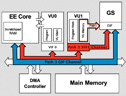
SPR stands for ScratchPad RAM. Think of it as a seperate block of fast memory for the EE. Here is a modified block diagram of all that is needed for SPR memory access.
Now, I feel like it’s important to note that are two ways to read/write to SPR.
- MMU mapped memory segment
- DMAC channels
The MMU mapped memory may sound complicated, but if you can understand basic C it’s very easy.
// SPR memory starts at address 0x70000000
u8* SPR_MEMORY = 0x70000000;
// Write some data to the SPR
SPR_MEMORY[0] = 0xFF;
SPR_MEMORY[1] = 0x00;
SPR_MEMORY[2] = 0xFF;
SPR_MEMORY[3] = 0x00;
// Congrats, you've just used SPR memory!
If we theoretically wanted to copy an entire texture to SPR we’d do the following.
u32 texture_to_transfer_size_qw = 0;
qword_t* texture_to_transfer = get_next_texture(&texture_to_transfer_size_qw);

process_texture(texture_to_transfer);

u128* SPR_MEMORY = 0x70000000;

for(int i = 0; i < texture_to_transfer_size_qw; i++)
{
	SPR_MEMORY[i] = texture_to_transfer[i];
}

free_texture(texture_to_transfer);
This is fine, it works, but the EE is stuck spinning in a loop transferring memory around. What if we let the DMAC take care of that while we continue to use the EE?
Finally. How to Use the DMAC
Each DMAC channel has the following registers.
- CHCR (Channel Control)
- MADR (Memory Address)
- TADR (Tag Address)
- QWC (QWORD Count)
The SPR channels have a special register.
- SADR (SPR Address)
A summary of how it works is as follows:
- Set MADR to your source/dest (TO/FROM channel respectively)
- Set QWC to the number of qwords (16 bytes) you want to transfer
- Set bit 8 (0x100) of CHCR to start your transfer
- Once bit 8 of CHCR is 0, the transfer has completed
Here’s an example of the theoretical texture upload using the DMAC. (I’ve simplified the channel register names. The actual ones can be located here).
-
u32 texture_to_transfer_size_qw = 0; qword_t* texture_to_transfer = get_next_texture(&texture_to_transfer_size_qw); process_texture(texture_to_transfer); // Point to the start of SPR *SPR_CHANNEL_SADR = 0x00; // Point to the start of our texture buffer *SPR_CHANNEL_MADR = texture_to_transfer; *SPR_CHANNEL_QWC = texture_to_transfer_size_qw; // Start the transfer *SPR_CHANNEL_CHCR = CHCR_STR; // Wait for the DMAC to finish while(*SPR_CHANNEL_CHCR & CHCR_STR) {}; free_texture(texture_to_transfer); // Somehow use the data in SPR -
u32 texture_to_transfer_size_qw = 0;
qword_t* texture_to_transfer = get_next_texture(&texture_to_transfer_size_qw);
process_texture(texture_to_transfer);

// libdma has no way to set SADR registers
// Point to the start of SPR
*SPR_CHANNEL_SADR = 0x00;

// Start the transfer
dma_channel_send_normal(DMA_CHANNEL_toSPR, texture_to_transfer, texture_to_transfer_size_qw, 0, 0);

// Wait for the channels transfer to end
dma_channel_wait(DMA_CHANNEL_toSPR, 0);
free_texture(texture_to_transfer);

// Somehow use the data in SPR
This does exactly what the MMU mapping example does above. Not very impressive. But! We can now incorporate some optimizations to keep the EE busy.
-
qword_t* transferred_texture = NULL; while(1) { u32 next_texture_size_qw = 0; qword_t* next_texture = get_next_texture(&next_texture_size_qw); if(next_texture == NULL) break; process_texture(next_texture); // Ensure that the DMA channel is not busy while(*SPR_CHANNEL_CHCR & CHCR_STR) {}; if(transferred_texture != NULL) { // Somehow use the data in SPR free_texture(transferred_texture); } // Point to the start of SPR *SPR_CHANNEL_SADR = 0x00; // Point to the start of our texture buffer *SPR_CHANNEL_MADR = next_texture; *SPR_CHANNEL_QWC = next_texture_size_qw; // Start the transfer *SPR_CHANNEL_CHCR = CHCR_STR; transferred_texture = next_texture; } // Somehow use the data in SPR free_texture(transferred_texture); -
qword_t* transferred_texture = NULL;
while(1)
{
	u32 next_texture_size_qw = 0;
	qword_t* next_texture = get_next_texture(&next_texture_size_qw);

	if(next_texture == NULL)
		break;

	process_texture(next_texture);

	// Ensure that the DMA channel is not busy
	dma_channel_wait(DMA_CHANNEL_toSPR, 0);

	if(transferred_texture != NULL)
	{
		// Somehow use the data in SPR
		free_texture(transferred_texture);
	}

	// libdma has no way to set SADR registers
	// Point to the start of SPR
	*SPR_CHANNEL_SADR = 0x00;

	dma_channel_send_normal(DMA_CHANNEL_toSPR, next_texture, next_texture_size_qw, 0, 0);

	transferred_texture = next_texture;
}

// Somehow use the data in SPR
free_texture(transferred_texture);
In this example we can load our next texture and do any processing to it while the previous texture is still uploading. This concept is known as double buffering.
While this post has covered the basics of the DMAC. For those interested in digging deeper into PS2 development, I encourage you to try DMATags. In most cases it’s a free optimzation. This is something I’m interested in covering next.
DMAC Notes
Caching was omitted from this post, you must ensure that you’ve flushed the data cache
before starting a transfer.
Alignment is a concern. MADR must be qword aligned. You can dynamically allocate
aligned data by using aligned_alloc. You can align a type by using __attribute__ ((aligned (16)));
I remember years ago looking at PSI-Rockin’s PS2Tek / GS Special Effects writeup and being curious how fast these clears perform in practice.
Spoilers: (This is when clearing a 640x448 32 bit framebuffer)
BigSprite: 79945 cycles
VIS Clear: 40567 cycles
Page Clear: 40496 cycles
Double Half Clear: 39199 cycles
Page Clear (double half clear): 20466 cycles
VIS Clear (interleaved): 18514 cycles
Interleaved Clear: 18399 cycles
Try it yourself or look at the code here on my GitHub: F0bes / clearbench
Clearly the winners are the interleaved clears, specifically the VIS Interleaved Clear though for reasons we’ll get into.
Interleaved Clear
To understand the VIS Interleaved Clear, we first have to understand what an interleaved clear is.
This clear relies on the fact that the memory in the GS is swizzled.
(TLDR: Memory is laid out in a way that is optimized for DRAM access.)
Because of this, the GS has memory access units called blocks, columns, and pages.
For this purpose we only need to worry about pages and the arrangement of blocks inside of a page.
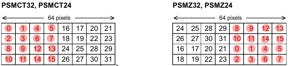
For these examples we will be using a CT32 and Z32 data format.
This leaves us with a page size of 64x32 pixels.
It’s important to note that Z testing / Z write is free on the GS. This means that there is no penalty for it being enabled.
Here is the block orientation in a page for a CT32 and Z32 data format*.
*CT formats are generally used for frame buffers and Z formats are generally used for the depth “Z” buffer.
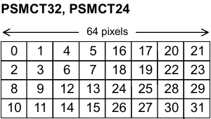
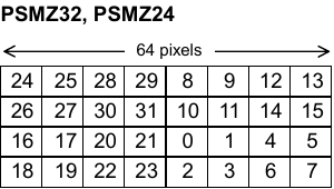
If you noticed, the blocks are mirrored horizontally and vertically between the Z and CT format. What’s really important here is the vertical mirroring.
Remembering that our page size is 64x32 pixels, what happens when we draw a 32x32 sprite from coords 0,0 to 31,31?
The red dots imply that the block has been written to.

(Don’t worry, I’m almost at the main point)
This is the result (the last frame of the animation) of the draw.
Now, the magic happens when we set ZBP = FBP.
I’ve indicated what is written by the colour write and the depth write.
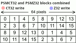
This results in the entire page (64x32 pixels, remember?) being modified, but we only needed to draw a 32x32 sprite!
Of course, our framebuffer isn’t 64x32 pixels. So a proper implementation of this would be something like the following.
const u32 page_count = 640 * 448 / 2048;

// fb_address doesn't have to be your frame, it can be any (page aligned) location in GS memory
// This clear can be used to clear out a depth buffer or a texture if you wanted to
GS_SET_FRAME(fb_address, ...)
// Ensure ZBP = FBP
GS_SET_ZBUF(fb_address, ...)

// We can only draw one page at a time. You have to at minimum kick two qw per page
// Set the clear colour here. This will be the colour of the first 32x32 pixels in each page
GS_SET_RGBA(0x00, 0x00, 0x00, 0x00)

for (int i = 0; i < 640; i += 64)
{
	for (int j = 0; j < 448; j += 32)
	{
		GS_SET_XYZ(i << 4, j << 4, 0x011E0000)
		// Our Z write is going to clear the second half of the 32x32 pixels in each page
		// Set our Z value to the clear colour
		GS_SET_XYZ((i + 32) << 4, (j + 32) << 4, 0x011E0000)
	}
}
This is probably good enough for most, but having to kick a sprite for each page gets memory expensive. Your GIF packet will be around 280QW :(.
What if I told you there is a way to get that down to ~16QW :).
The VIS Clear
If you were wondering, the VIS Clear name is attributed to the engine used by VIS Interactive / VIS Entertainment. Apparently this engine liked this clear.
Let’s look at how pages are arranged in a frame and zbuffer.
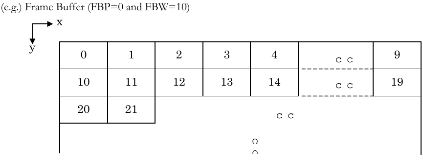
By changing the FBW (Frame Buffer Width) size in the GS FRAME register, you can change how many pages make up the width of the frame. What happens if we set FBW to 1?
And this is exactly what the VIS clear does.
I just want to note, this suucckkss to emulate on a GPU.
Now that our framebuffer is a 64x4480 strip of memory*, we can draw very tall sprites, covering many pages.
Because the maximum height of a sprite is 2048 pixels, the framebuffer pointer needs to be moved after every sprite.
*In the case of a 640x448 framebuffer
The non-interleaved VIS clear would draw a few 64 width sprites going all the way down the framebuffer. But we can utilize our interleaved trick to only have to do 32 width sprites.
The Interleaved VIS Clear
At the moment I can’t seem to figure out a good way how to animate this process.
Here is my implementation of an interleaved VIS clear.
// Set the clear colour here
GS_SET_RGBA(0x00, 0x00, 0x00, 0x00)
// Set the ZBP and ZBP to the start of the memory you want to clear
// (in this case the framebuffer)
GS_SET_FRAME(fbptr, 1, GS_PSM_32)
GS_SET_ZBUF(fbptr)
GS_SET_XYZ(0, 0, 0x00000000)
GS_SET_XYZ((32 << 4), 2048 << 4, 0x00000000)
// Because a height of 2048 covers 64 pages (each page is 32 pixels high)
// Increment our FBP and ZBP by 64
GS_SET_FRAME(fbptr + 64, 1, GS_PSM_32)
GS_SET_ZBUF(fbptr + 64, GS_PSMZ_32)
GS_SET_XYZ(0, 0, 0x00000000)
GS_SET_XYZ((32 << 4), 2048 << 4, 0x00000000)

// Increment another 64 pages
GS_SET_FRAME(fbptr + 128, 1, GS_PSM_32)
GS_SET_ZBUF(fbptr + 128, GS_PSMZ_32)
GS_SET_XYZ(0, 0, 0x00000000)
// 384 comes from (640 * 448 / 64) % 2048
GS_SET_XYZ((32 << 4), 384 << 4, 0x00000000)
Including GIFTAGs, this is method is only around 16QW. That’s around 17 times less than the normal interleaved clear. This gives you good GS fill speed without as much bus contention from DMAC usage.
Final Thoughts
If you missed it above, you can view the code to the clears in my clearbench repository on GitHub: F0bes / clearbench
Hopefully you’ve gained some understanding about these clears. If anyone wants me to to cover any of the other clears mentioned above let me know. Do know that the ones covered here are easily the most complex.
]]>The final source is located on my GitHub here.
I found a post long ago about an effect 8-bit game developers would use for animations.
Randomly remembering it, I decided I will try to do the same using the indexed texture and CLUT feature of the PlayStation 2’s GS.
* Note that CLUT is an acronym for Colour Look Up Table and is used interchangeably with ‘palette’
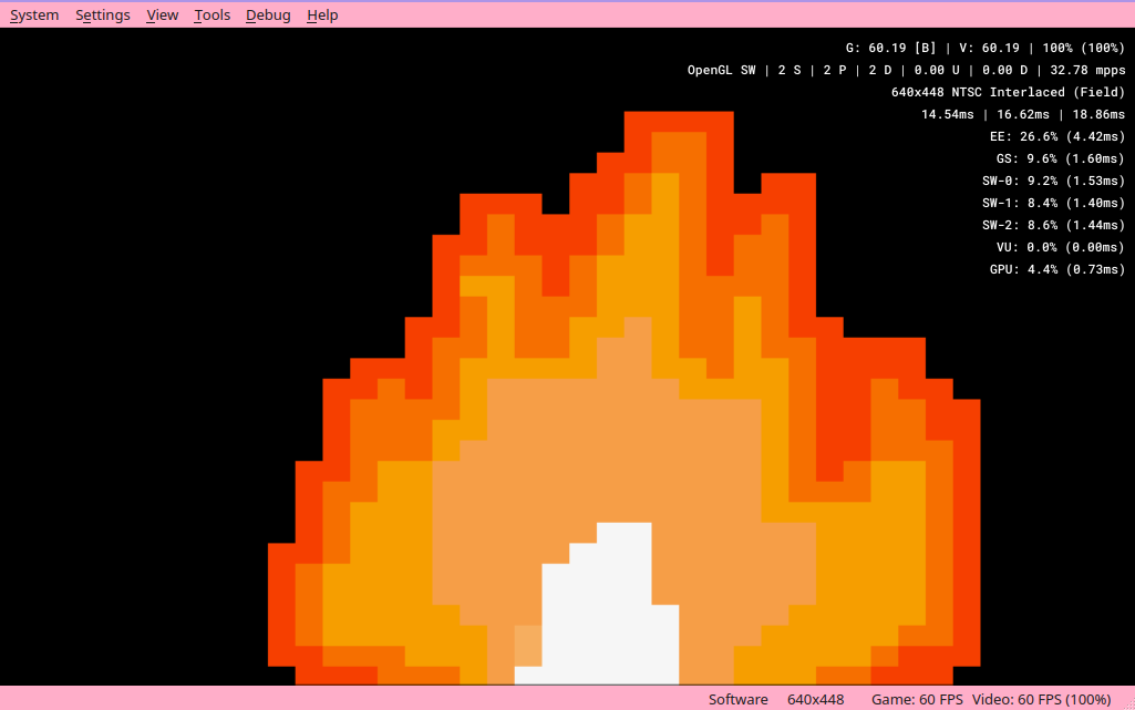
First off, I needed something to animate. Inspired by a piece of homebrew (created 1 month after me o_o) I went with a flame.
Fully aware that I wouldn’t be able to recreate something that cool, I went to GIMP and ended up with this.

Pretty snazzy, right?
Now, if you’re unsure what a colour palette is, I’ll do my best to explain. If you do know, feel free to skip this next segment.
Palette Basics
Let’s assume that we are using texture format PSMCT32.
8 bits for A, B, G and R each. That’s 32 bits, or 4 bytes per texel.
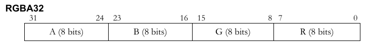
If we do the math, a 512x512 texel texture will take ~1 MB of memory. Now for the PS2, that’s a quarter of the VRAM the GS has, ouch.
Thankfully though we can change how our texels are interpreted. Instead of each texel being a packed ARGB value, we can instead treat each texel value as an index into a table. That table is otherwise known as a palette.
Here is some spreadsheet artwork to aid my explaination
On the left hand side is our palette. It currently only has indexes 0->4 loaded with a colour. On the right hand side is our texture. Each texel (or cell in this case) references a colour in our palette.
Now, the PS2 has two different types of indexed textures, 4 bit and 8 bit. What one should be used? It depends on how many colours you need. An indexed texture can only reference 16 (4 bit) or 256 (8 bit) colours depending on the mode you use.
If we utilise a 4bit indexed format, our 512x512 texture mentioned above is now 131KB instead (with another 256 bytes for the palette)*.
Hopefully you have a little bit more of an understanding of how a palette and indexed texture works.
* This section completely ignores the existence of CT24 and CT16 colour formats for simplicity.
The Implementation
To create the indexed texture, I simply used GIMPs indexed texture mode. Because there is no native support in GIMP for a 4 bit mode, I had to write a python script to convert the 8 bit format into a 4 bit one.
With some manual labour out of the way, I had two arrays of data.
My palette.
u16 flame_clut[16] __attribute__ ((aligned (16))) =
{
	0x9CE7,
	0x811F,
	0x81DF,
	0x829F,
	0xA69F,
	0xA69F,
	0xB2DF,
	0xFFFF,
	0x0000,
	0x0000,
	0x0000,
	0x0000,
	0x0000,
	0x0000,
	0x0000,
	0x0000
};
My texture.
static u8 flame_itex[] __attribute__ ((aligned (16))) =
{
	0xBB, 0xBB, 0xBB, 0xBB, 0xBB, 0xBB, 0xBB, 0xBB,
	0xBB, 0xBB, 0xBB, 0xBB, 0xBB, 0xBB, 0xBB, 0xBB,
	0xBB, 0xBB, 0xBB, 0xBB, 0xBB, 0xBB, 0xBB, 0xBB,
	0xBB, 0xBB, 0xBB, 0xBB, 0xBB, 0xBB, 0xBB, 0xBB,
	0xBB, 0xBB, 0xBB, 0xBB, 0xBB, 0xBB, 0xBB, 0xBB,
	0xBB, 0xBB, 0xBB, 0xBB, 0xBB, 0xBB, 0xBB, 0xBB,
	0xBB, 0xBB, 0xBB, 0xBB, 0xBB, 0xBB, 0xBB, 0xBB,
	0xBB, 0xBB, 0xBB, 0xBB, 0xBB, 0xBB, 0xBB, 0xBB,
	0xBB, 0xBB, 0xBB, 0xBB, 0xBB, 0xBB, 0xBB, 0xBB,
	0xBB, 0x11, 0x11, 0xBB, 0xBB, 0xBB, 0xBB, 0xBB,
	...
Note: There are alignment constraints when using the PS2s DMAC. Make sure your data is at least QWORD (128 bit) aligned!
After some display initialization and vram allocations, I was ready to upload my CLUT, texture, and my draw.
Well, it’s a start.
Now it’s time to rotate the clut. All this does is shift every colour backwards every odd frame.
void rotate_palette()
{
	u16 *colour_palette = (u16 *)UNCACHED_SEG(flame_clut);
	u16 first_index = colour_palette[0];
	for (s32 i = 1; i < 0xF; i++)
		colour_palette[i] = colour_palette[i + 1];
	colour_palette[0xF] = first_index;
}
That’s cool, but not what I wanted. Instead of rotating the entire palette, let’s only rotate the colours used inside of the flame.
// Rotates the palette from indices 1 to 6
void rotate_palette()
{
	u16 *colour_palette = (u16 *)UNCACHED_SEG(flame_clut);
	u16 temp = colour_palette[0];
	for (s32 i = 0; i < 0xF; i++)
		colour_palette[i] = colour_palette[i + 1];
	colour_palette[0xF] = temp;
}
That’s good enough for me. But flames usually move right? Using GIMP’s smudge tool, I generated 3 different textures (all using the same palette).


After some testing, swapping between these textures every 5 frames provided some pretty good results.
The Technical Part
To keep this post somewhat friendly, I opted to leave the heavy PS2 specific details out of the main portion. If you’re not interested in how I used the VIF, DMAC GIF and GS, or if you don’t know what any of those mean, this part might get boring.
There are 3 data paths to the GS.
- PATH3 is directly from the EE to the GS
- PATH2 is from the EE to the VIF1 and to the GS
- PATH1 is from VU1 memory to the GS
PATH3 is the easiest. Build a GIF packet and send it to the GIF via DMA channel 2.
* Or directly write to the FIFO, which I’m not going to bother entertaining in this post.
At the time of writing this code, I did not have much experience using PATH2. I decided that I’m going to finally use PATH2 for something.
Credit: Guilherme Lampert
My design ended up becoming this
The sprite packet is actually two sprites.
// (psuedo code)
GIF_SET_TAG(9, 1, GIF_PRE_ENABLE, GS_PRIM_SPRITE, GIF_FLG_PACKED, 1)
GS_SET_RGBAQ(0x00, 0x00, 0x00, 0x7f, 0x00)
GS_SET_XYZ(0 << 4, 0 << 4, 0)
// Sprite kicked, clears the framebuffer with black
GS_SET_XYZ(640 << 4, 448 << 4, 0)

// Set our primitive to a sprite, textured, using UVs, Alpha blending enabled
GS_SET_PRIM(GS_PRIM_SPRITE, 0, 1, 0, 1, 0, 1, 0, 0)

// Point to our texture and clut buffer
GS_SET_TEX0(g_texptr / 64, 1, GS_PSM_4, 5, 5, 1, 1, g_clutptr / 64, GS_PSM_16, 1, 0, 1)
GS_SET_UV(0, 0)
GS_SET_XYZ(0, 0, 0)
GS_SET_UV(32 << 4, 32 << 4)
// Sprite kicked, UV 0,0 to 32,32 will be mapped to 0,0 -> 640,448
// The GS takes care of mapping the texture to the clut buffer
GS_SET_XYZ(640 << 4, 448 << 4, 0)
Kicking this is very simple.
- Flush the cache!
- Set DMAC channel 2 MADR to the start of the packet
- Set DMAC channel 2 QWC to the length of the packet in qwords
- Set DMAC channel 2 CHCR to 0x100 to start the transfer
Or just use the dma lib and call
dma_channel_send_normal(DMA_CHANNEL_GIF, draw_packet, q - draw_packet, 0, 0);
I’ll skip explaining the rotating parts in depth. You’ve already read above what rotating the palette involves. Rotating the texture is simply changing a global pointer between the 3 texture arrays. Unlike the palette, the textures are not modified during runtime.
Now, uploading the palette and texture. I utilised something called DMA chains. Instead of transferring one big block of memory, starting from MADR and ending at MADR + QWC, our DMAC can be smart and do some heavy lifting for us.
I’ve simplified this code as best as I could. If it looks intimidating, you’d be right, it is.
// Tell the DMAC to send the next 7 QW in this packet to the VIF
DMATAG_CNT(q, 7, 0, 0, 0);
	// Tell the VIF to send the next 8 QW to the GIF
	PACK_VIFTAG(q, VIF_CMD_NOP, VIF_CMD_NOP, VIF_CMD_NOP, (VIF_CMD_DIRECT << 24) | 8);

		// Tell the GIF that we will be 'blit'ing a texture
		GIF_SET_TAG(4, 0, 0, 0, GIF_FLG_PACKED, 1)
		GS_SET_BITBLTBUF(0, 0, 0, g_clutptr >> 6, 1, GS_PSM_16)
		GS_SET_TRXPOS(0, 0, 0, 0, 0)
		GS_SET_TRXREG(16, 1)
		// As soon as we set TRXDIR, the GIF treats the incoming data as a texture
		GS_SET_TRXDIR(0)

		// Tell the GIF that the next 2 QW will be in IMAGE format
		GIF_SET_TAG(2, 0, 0, 0, GIF_FLG_IMAGE, 0)

// This is where things get interesting
// Instead of copying the data at flame_clut into this packet (which can be expensive in memory and execution time the larger your data is)
// The DMAC engine will start copying data (2 qw) from starting from flame_clut
// It's REFerencing to flame_clut
DMATAG_REF(q, 2, (uiptr)flame_clut, 0, 0, 0);

// I've excluded uploading the texture in this sample. It is essentially the same exact thing.
To rephrase; if your texture is a huge amount of QW, you can simply reference it instead of copying it all into your dma packet.
In another effort in explaining the DMAC chain, here is a diagram of what is hapening above.
Numbered is the data that gets sent to the GIF.
Kicking this is even easier.
- Flush the cache!
- Set DMAC channel 2 TADR to the start of the packet
- Set DMAC channel 2 CHCR to 0x104 to start the tag trasnfer
Or just use the dma lib and call
dma_channel_send_chain(DMA_CHANNEL_GIF, draw_packet, q - draw_packet, 0, 0);
Final Thoughts
If you’ve made it this far, thank you! I’m still trying to figure out how I want these posts to be written. I don’t want to write things nobody understands but I also want to keep it interesting without culling too many details.
If you’d like to play around with the code, it’s located on my GitHub here.
I’m happy to say the original iteration of the “VIF Flame” inspired Daniel Santos to implement it into their GTAV PS2 recreation. You can check out the demo on their youtube channel.
Link here if the above doesn’t work https://www.youtube.com/watch?v=9TLH5kXNGZw